
Mechanical Drawing Symbols
1 Clarity And Conciseness Engineering drawings often contain a large amount of information, including dimensions, tolerances, annotations, and other details. Using abbreviations and symbols allows for concise representation, making the drawings easier to read and understand. 2 Standardization
Mechanical Engineering Drawing Symbols Pdf Free Download at Explore
Mechanical Engineering solution — 8 libraries are available with 602 commonly used mechanical drawing symbols in Mechanical Engineering Solution, including libraries called Bearings with 59 elements of roller and ball bearings, shafts, gears, hooks, springs, spindles and keys; Dimensioning and Tolerancing with 45 elements; Fluid Power Equipment.
Mechanical Engineering Drawing Symbols Pdf Free Download at Explore
MEC076 Engineering Drawing Interpretation 1 Resource Package December, 1998 h'" iI 'II I MEC076 -10 -1 I 131 Basic and Common Symbols. Recognition. The symbols covered in on the following pages are an example of the widespread use of symbols and abbreviations in industry.
Mechanical Engineering Solution
Engineering drawing abbreviations and symbols are used to communicate and detail the characteristics of an engineering drawing. This list includes abbreviations common to the vocabulary of people who work with engineering drawings in the manufacture and inspection of parts and assemblies.

Engineering Drawing Symbols And Their Meanings Pdf at Explore collection of
1 Check the title block for basic information about the drawing. The title block appears either at the top or bottom of an engineering drawing. Read this first to find out crucial information about the drawing, including: [4] The name and contact information for the company producing or distributing the part

Engineering Drawing Symbols And Their Meanings Pdf at Explore collection of
The following is a summary of the principal changes and improvements incorporated in this issue: a. Addition of Composite Material Drawing definition. b. Changing of the signature to a printed name in Title blocks. c. New example of the Metric Drawings format and tolerance presentation. d.

Mechanical Drawing Symbols
These abbreviations can be found on engineering drawings such as mechanical, electrical, piping and plumbing, civil, and structural drawings. Common abbreviations include AC (alternating current), DC (direct current), FAB (fabrication), and LD (load). As an integral part of CAD/CAM technology, CNC design is used to develop and produce products.

Mechanical Engineering Drawing Symbols Pdf Free Download at Explore
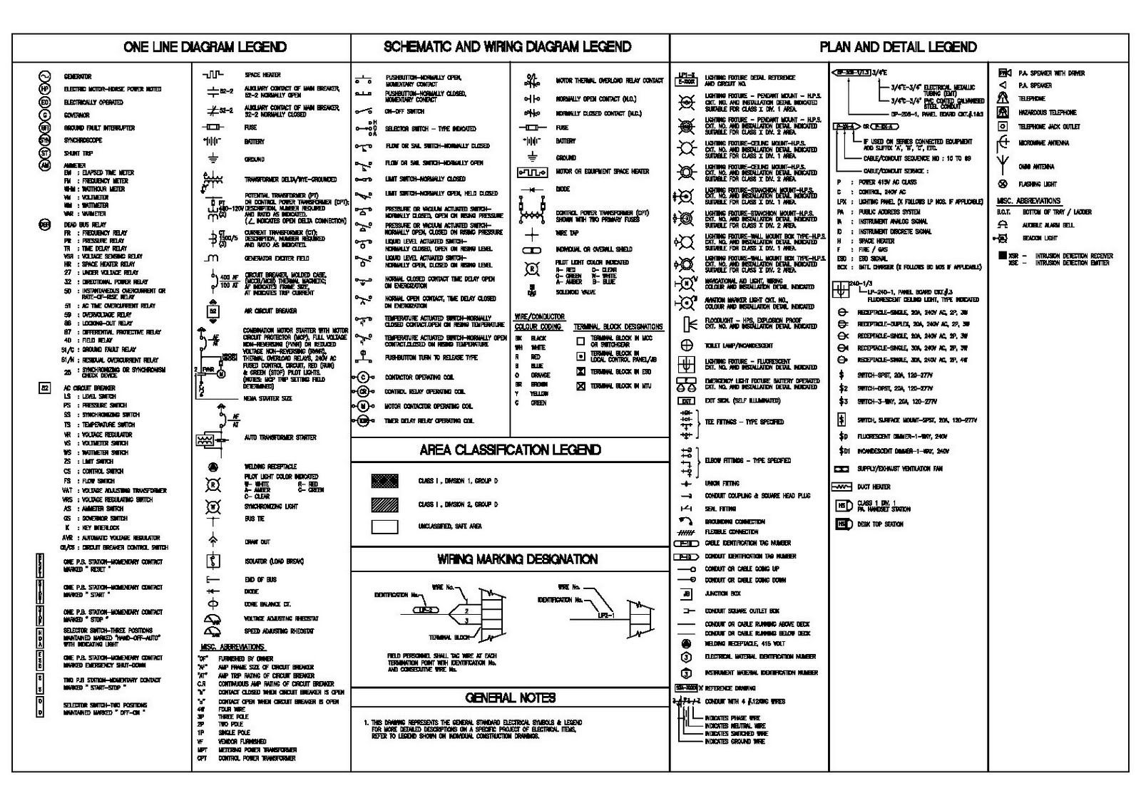
Graphical symbols for use on mechanical engineering and construction drawings, diagrams, plans, maps and in relevant technical product documentation. 01.080.40. Graphical symbols for use on electrical and electronics engineering drawings, diagrams, charts and in relevant technical product documentation. 01.080.50.

Mechanical Engineering Drawing Symbols Pdf Free Download at GetDrawings Free download
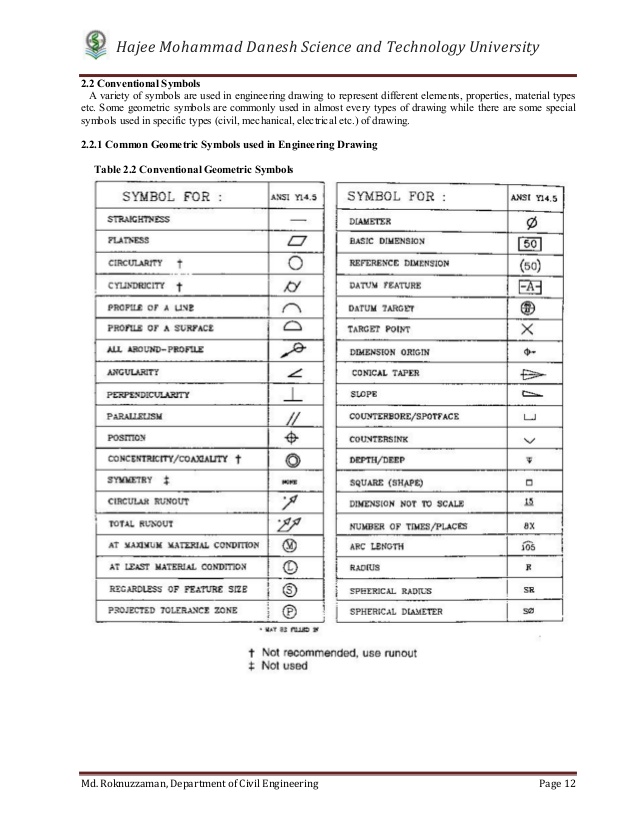
The following is a list of symbols used for geometric tolerancing. "Single feature" under "Feature level" means features that are independent of datums (i.e. that do not require reference datum indication). A datum is a theoretical, ideal feature established to determine the orientation, location, and/or run-out.

M&e Drawing Symbols Back To Basics Komseq
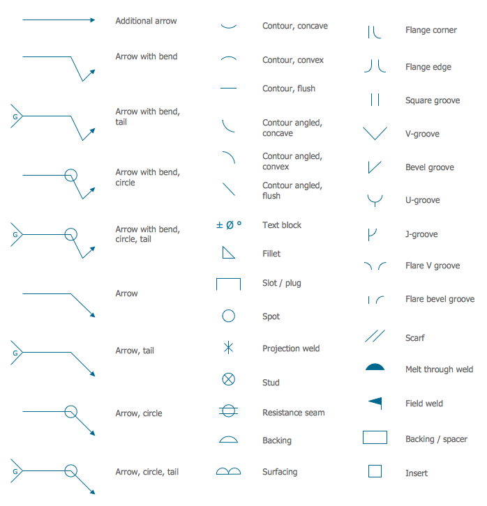
Valve Assembly The vector stencils library "Valve Assembly" contains 141 symbols of pressure and flow regulators, flow direction indicators, controls, and symbols to design flow paths of control valves. Use these valve assembly shapes to design the engineering drawings of hydraulic and pneumatic valve assemblies in fluid power systems. Welding

Engineering Drawing Symbols And Their Meanings Pdf at Explore collection of
2018 - ASME Y14.5 Of companies in the US, Canada, and Australia that have adopted the ASME standard, approximately half are using the 2009 version, and over a quarter still use the 1994 publication. A relatively small percentage of companies are using the 2018 version.
Mechanical Engineering Drawing Symbols Pdf Free Download at Explore
This solution extends ConceptDraw PRO v.9 mechanical drawing software (or later) with samples of mechanical drawing symbols, templates and libraries of design elements, for help when drafting mechanical engineering drawings, or parts, assembly, pneumatic, Mechanical Symbols Chart Pdf

Mechanical Engineering Drawing Symbols Pdf Free Download at Explore
Artificial Intelligence (AI) Learn how to use symbols and abbreviations in mechanical drawings for engineering design. Find out the benefits, challenges, and tips for using them.

Mechanical Engineering Drawing Symbols Pdf Free Download at Explore
Position Symbol (⊕): The position symbol is used to indicate the allowable deviation in the location of a feature. Concentricity Symbol ( ): This symbol signifies that two or more cylindrical features must share a common center axis.

GD&T Symbols Reference Guide from Sigmetrix Mechanical design, Engineering design, Technical
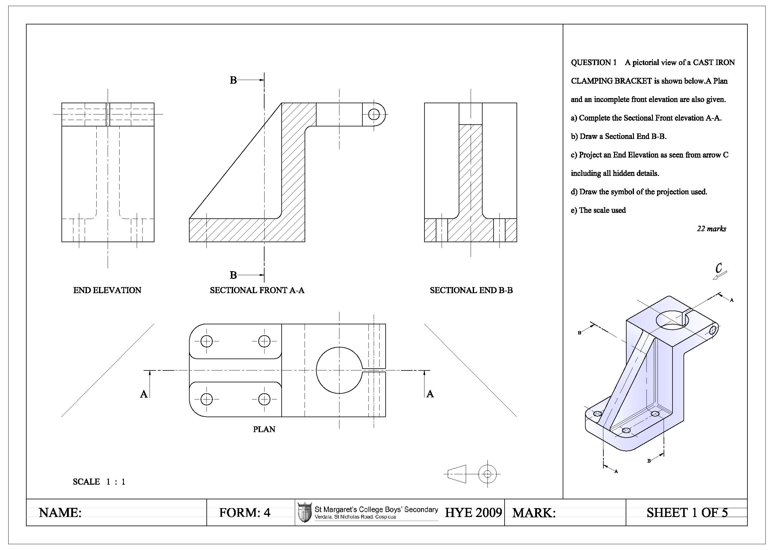
Engineering Working Drawing Basics is a pdf document that introduces the fundamental principles and practices of engineering drawing. It covers topics such as types of drawings, symbols, dimensions, tolerances, and views. It is a useful resource for students and engineers who want to learn or review the basics of engineering drawing.

Engineering Drawing Symbols And Their Meanings Pdf at Explore collection of
C'BORE or CBORE: Counterbore CYL: Cylinder or Cylindrical DATUM: Datum System ": Degree (of angle) DIA: Diameter DIM: Dimension DRG: Drawing ENG: Engine, engineering EQUI SP: Equally Spaced EXT: External FIG: Figure FT: Foot GAL: Gallon GALV: Galvanized HRA: Hardness Rockwell A scale